Design and Analysis of a COPV
- Ned Patton
- Apr 23, 2023
- 5 min read
So, you want to make a COPV because you know that it will be lighter weight, more resistant to violent burst if it does burst, and you can make it fit your application. Essentially you have made this decision because you need to store some gas at high pressure and a steel air tank for that pressure and capacity would be too heavy, too large, or just won’t work for your application. This is typically true for vehicle applications, including boats – effectively for something that needs to move and carry its gases with it.
What, exactly, do you need to know before you get started? This is where the COPV designer makes their critical decisions. And I am going to apologize at the outset, there’s a little math, physics, and materials engineering in this post, so hang on, I’ll provide it as gently as I can.
· First, you need to know how much room you have to install this COPV – essentially where is it going to be used and what is it attached to.
· Next, you need to know what pressure you want this thing to operate at, and what is going to be stored inside the COPV. Is it air? Is it Oxygen, Nitrogen, Hydrogen, LNG, or some other specialty gas that you need to store at high pressure.
· Now you need to know how much of this gas you need to store
· This leads you to deciding on what pressure you need to use in your design as what is called Maximum Expected Operating Pressure or MEOP
· Finally, you need to know what National or International Standard you need to use to design and fabricate your COPV.
So, let’s first talk about the Standards for COPVs. There are two Nationally and Internationally accepted Standards for the design, fabrication, and qualification of COPVs.
The first and most used Standard is ANSI/AIAA S-081B (2018). The (2018) means that this is the version of the Standard that was adopted in 2018, and it is the most current version of the Standard. This Standard is used throughout the aviation industry, commercial and military, and by NASA and DOT. This means that every COPV that goes into a rocket is qualified to this standard, as well as every COPV that goes into an aircraft – both military and civilian. And, the LNG tanks on tanker truck and rail cars are also designed, fabricated, and qualified to this Standard. One of the things that this Standard requires is that the fabricator has to burst test two of the same design COPVs before the COPV design can be qualified.
The other Internationally accepted Standard is from the ASME Boiler and Pressure Vessel (B&PV)Code. Metallic pressure vessels are built and certified to Section VIII, Divisions 1, 2 and 3 of this Code. Division 2 pressure vessels are high pressure metal pressure vessels that operate at pressures similar to the pressures of most high pressure COPVs. Section X (yes, that’s Section 10) is the part of the ASME B&PV Code that addresses COPVs.

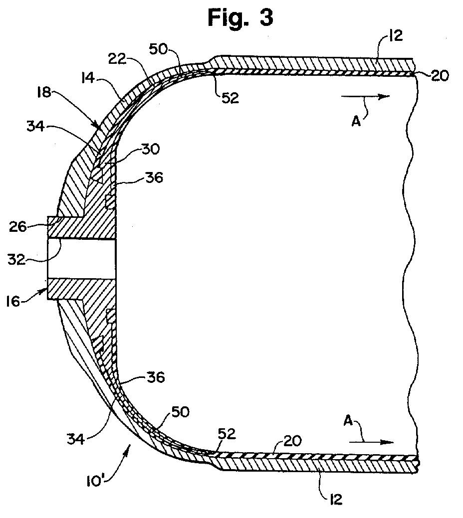
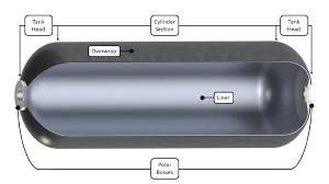
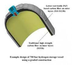
Now that you have decided what Standard you are going to use, how big the vessel is, what it is going to contain, and what at what pressure it is going to operate, you need to decide what you are going to make it out of. And, since this is a Composite Overwrapped Pressure Vessel, the first material you need to choose is the liner material. Most commonly this is going to be aluminum – and the alloy most commonly used is 6061-T6 (6061 defines the chemistry of the alloy, and T6 is the temper designation).
For our purposes let’s say that we have chosen 6061 T6 as our aluminum liner material and a medium modulus carbon fiber (say Toray T800) and an epoxy resin system that is compatible with the carbon fiber. First, the liner of a COPV doesn’t carry much of the load of the pressure vessel – especially in what is called the “hoop” direction. This is the stress in the direction of the circular portion of the pressure vessel – around the perimeter.
A small aside here about pipelines and pressure vessels – the hoop direction stress is twice the stress in the long direction of the pressure vessel or pipeline, and is the product of the Pressure times the Radius of the cylinder divided by the thickness of the wall of the cylinder – or P*R/T. The long direction stress is half that or P*R/2T.
So, our liner is usually designed to largely carry mostly the long direction stress, and the composite overwrap is designed to carry mostly the hoop stress. This is somewhat of a simplification, but it is a good place to start to determine what thickness of each material we need to design our pressure vessel.
Let’s say that we have a 12 inch diameter pressure vessel that is operating at 4000 psi. Our composite overwrap has an allowable stress of 100,000 psi, and the 6061-T6 liner has an ultimate strength of ~50,000 psi. What we do is rearrange our hoop stress equation because we need to know the thickness of the liner and the overwrap. And it isn’t a bad idea at least at the start to assume that the aluminum doesn’t carry any load in the hoop direction.
So – the composite thickness will be:
Pressure * Radius / Allowable Stress = 0.24” – so to be safe let’s make it .25 inches.
Now for the aluminum liner. Let’s assume that the liner gets just to yield strength at the operating pressure of the air flask. So, again rearranging:
Thickness = Pressure * Radius / (Yield Strength * 2) = 0.24”.
Since we can let the aluminum liner yield a bit against the composite, we can actually use 0.2” for the liner thickness. At the domed ends of the pressure vessel, we can thicken up the aluminum a little bit to handle more of the pressure load (as in the pic at the top of this post). And, the composite is not only wound on around the cylindrical part of the vessel (hoop windings), it is also wound around the ends in a helical fashion. The angle of these windings is usually calculated as the arcsine of what is called the polar diameter (the diameter of the nipple that sticks out the end where you fill and empty the pressure vessel), divided by the outside diameter of the pressure vessel. Common helical wind angles go from about 25 degrees to about 55 degrees depending on the size of the opening at the end of the flask compared to the outer diameter of the straight section. And since the helical windings go the entire length of the pressure vessel, they carry not only the hoop direction load, they also carry some of the long direction load.
In last week’s newsletter I had a pic of a COPV being fabricated on a filament or tape winding machine. One of the pics in that newsletter showed both the hoop windings and the helical windings. I like that pic, so I’m including it here just to remind everyone how these pressure vessels are designed and made.

Now that you understand how a COPV is designed, the angle of the fibers that you see at the right end of this picture should be pretty obvious to you. These fibers are carrying largely the long direction load whereas the windings that go around the pressure vessel to the left in the picture are carrying mostly the hoop direction load.
That is about enough for this post, so I’ll stop here. In the next post in this series I need to continue this discussion and talk about analysis of a COPV and a bit about how that analysis drives what is called the “Autofrettage” pressure, and what this means. It is something that is done as a last step in the manufacturing process. And I am also going to talk about the qualification analysis, process control, and testing that is required in both of the Standards.
Comments